

Sometimes after giving my station report, another operator will comment on my claim of a ‘modified‘ IC-7300 and/or “average PEP to the antenna is 130 to 140 Watts”— and ask how I accomplish this safely. The answer to this concerns a simple modification to the IC-7300 (first published in 2016 by Gregorz SP3RNZ) which has proven to be beneficial and safe across the 10-year production cycle of the IC-7300, and is currently found in widespread amateur usage. Combined with proper adjustments of power, mic gain, EQ and compression–this will not turn one’s rig into a splatter box, nor let the magic smoke out. Let’s take a deep dive into the theory, circuit design, and execution of this mod!
HOW IT WORKS
The IC-7300’s transmit ALC (Automatic Level Control) is a feedback system that keeps the transmitter from trying to produce more RF drive than the PA and its operating conditions can safely handle. The two most important things to remember is that the ALC in the IC-7300 is not simply an audio compressor—and that it is one of the few analog circuits in the radio. The latter fact is what allows ALC circuitry modifications to be made without bumbling about in the service menu settings. There is a firmware route to accomplish this, along with expanding ESSB bandwidth up to 3.2Khz. My take on fiddling with firmware is unless one has a way to backup and restore the original version–and possess the equipment and encoding knowledge to effect such things is to not do so. The former software change raises the base limit of the rig beyond 100 watts, and is a recipe for trouble–which can be avoided by not screwing about and choosing a method that does not routinely kill the automatch or PA board with a golden screwdriver fix…
The goal of this modification is not to raise the base power beyond 100 watts–but rather to deliver a fuller signal that does not try to hammer down on the audio peaks.
An analysis of the ‘rated’ component limits finds 175 watts peak to be the upper limit of safety—but note that this does not apply to the internal automatch—which begins to manifest issues above 150 watts PEP! Proper outboard matching is another key practice here with using the mod. This is due to the ratings of the fast switching LC relays. As to the overall rig itself, it will often draw 24 amps or a fraction more. This sort of current draw poses a significant risk for something that is a completely insignificant gain. It’s best to shift to an external automatch of at least 200 watts rating, such as the LDG AT-200 or similar. Let’s consider the basic signal path:
Microphone/audio → DSP/modulator → RF drive stages → PA → RF output
and alongside that:
RF level sensing → ALC detector → control voltage → earlier RF stages
We find that the ALC circuit is a negative-feedback loop. When the transmitter is operating below its software limiting point, the ALC has little or no effect. As the RF level approaches the limit established by the radio’s power-control system, the ALC control voltage changes the gain of an earlier stage and reduces the drive. In simplified form:
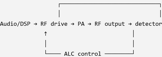

What the ALC meter actually represents
This is an important distinction.The ALC meter isn’t a direct correlation to output watts. It indicates the amount of ALC control being applied. So, for example, if you have the IC-7300 set for 50 W and your modulation/drive would otherwise make the transmitter produce more than that, the ALC loop backs the drive down. If you reduce the RF POWER setting, you’re effectively moving the ALC operating point. The exact behavior depends on mode and signal characteristics–and note that this does not ‘increase’ the natively programmed power–but rather allows the PEP to rise with less clamping control.
On this radio, the ALC system isn’t solely there to make voice modulation behave nicely and put on a big Part 97 show. The transmitter also monitors conditions associated with the PA, including output power/SWR-related conditions. Icom describes the PA unit as containing both the power amplifier and sensing circuitry for transmit power and SWR. If the PA suddenly sees a condition where it shouldn’t continue receiving the same amount of drive, the ALC system can rapidly reduce the drive. That’s why modifying the ALC behavior of an IC-7300 can have consequences beyond simply “getting more average power.” There are documented cases where ALC modifications produce excessive power overshoot and interfere with the intended protection behavior.
Because the IC-7300 is predominantly an SDR architecture, the ALC isn’t necessarily operating the way you might imagine, however it is one of the few analog circuits in the radio. The DSP establishes much of the transmit waveform, while the RF circuitry provides gain and power amplification. The ALC system can therefore control the RF chain at appropriate points rather than simply turning microphone audio down.
That distinction becomes especially interesting when looking at SSB versus FT8/RTTY versus CW, because the waveform’s peak/average characteristics are very different. So then, how does modifying the ALC circuit by the addition of a tantalum capacitor such as the SP3RNZ modification work? Gregorz modification is actually quite clever, in that it doesn’t increase the IC-7300’s maximum RF output power; it changes the time response of the ALC loop so that the transmitter doesn’t clamp the SSB envelope quite as quickly. SP3RNZ specifically describes it as an “ALC slowdown” modification.
So what does adding a capacitor really do? The modification adds roughly 2.2–4.7 µF of capacitance at a particular point in the IC-7300’s ALC circuit. SP3RNZ reports 3.3 µF as a good compromise, with 4.7 µF producing a somewhat slower response. After much testing with various audio chain components and settings, I have settled on the 4.7uf cap after initial experiments with other values.
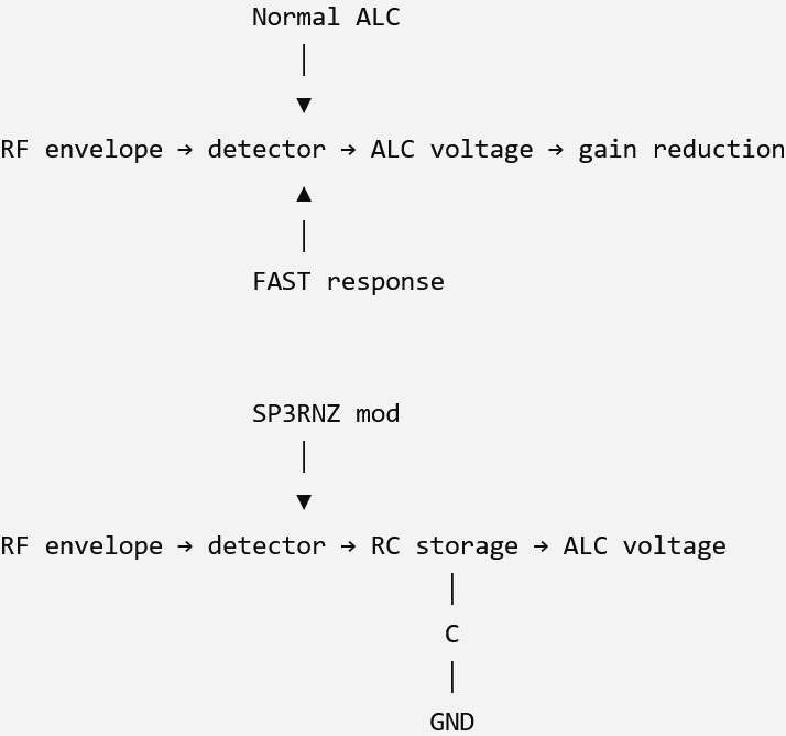
The added capacitor effectively makes the ALC control voltage change more slowly. In control-system terms, you’re adding additional low-pass filtering / integration to the ALC feedback path. Why then does this increase the average SSB power? This is the really interesting part. Consider an SSB waveform containing alternating loud and quiet portions:
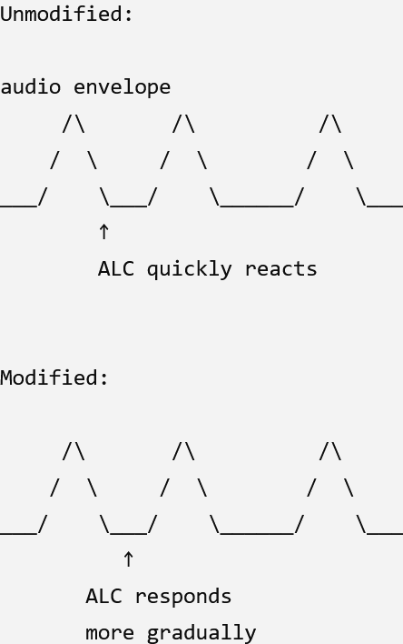
With the factory set ALC response, a large instantaneous peak can cause the ALC to pull the RF gain down very quickly. When the peak disappears, the ALC subsequently releases. That can reduce the amount of RF energy delivered during the portions of speech immediately following the peak. The SP3RNZ modification makes that control action slower. Consequently, short-duration speech peaks don’t cause the transmitter gain to collapse as abruptly, allowing more of the following envelope to pass at a higher level. SP3RNZ says this is why the modification increases average or “talk” power rather than maximum peak power. Think of it as changing the ALC “reaction time” The diagram below is probably the easiest way to understand it. Imagine the ALC sees:
LOUD → quiet → loud → quiet
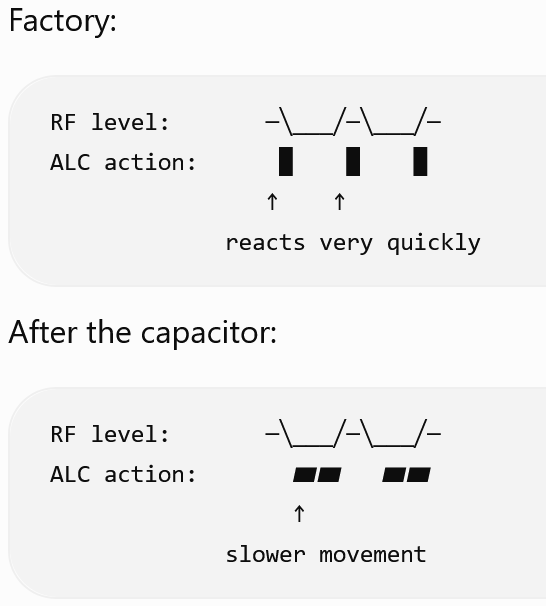
The capacitor doesn’t tell the transmitter “Make more power.” Instead, it tells the ALC “Don’t react quite so rapidly to every envelope excursion.” That’s why the modification can produce substantially more average SSB power while the radio’s fundamental maximum output capability remains essentially unchanged. This is where SP3RNZ’s choice of 2.2–4.7 µF makes sense. The effective ALC response time is determined by the capacitance together with the resistance/impedance around that node. In a simplified RC system:
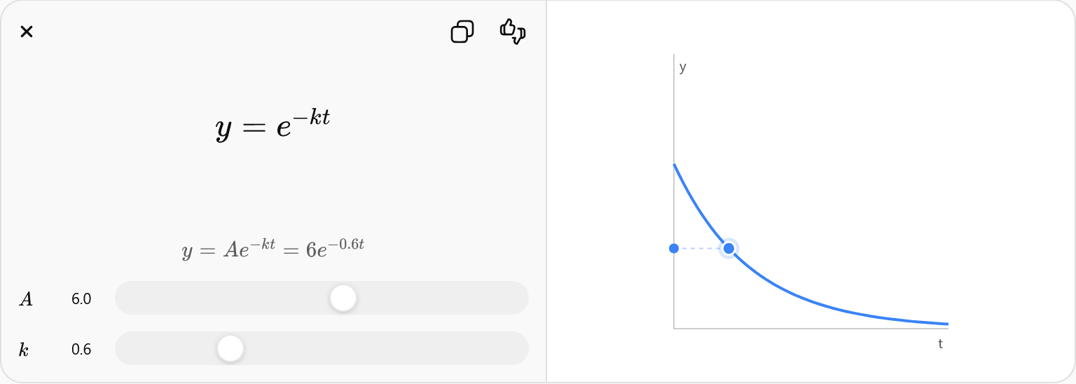
A larger capacitor means the control voltage has more electrical “inertia.” So, approximately:
- 2.2μf → less slowing
- 3.3μf → intermediate
- 4.7μf → more slowing
SP3RNZ specifically reports 3.3µF as an optimal compromise from testing. But, there is an important tradeoff. There’s a reason Icom made the ALC relatively fast. ALC is ultimately protecting the transmitter from excessive drive and helping maintain controlled modulation. If you make it too slow, the transmitter can potentially spend more time at excessive drive before the control loop catches up. That’s why “more average power” doesn’t automatically mean “better transmitter performance.” There’s a sweet spot to be found:
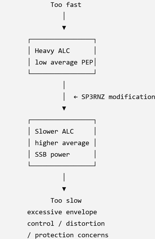
Grzegorz’s own documentation therefore recommends the modification with considerable caution and emphasizes that the soldering is on very small SMD components.
MAKING THE MODIFICATION
****DISCLAIMER: WORKING WITH SMD CAN CAUSE SEVERE, IRREPARABLE DAMAGE TO YOUR RIG. ALL POSTS AND INFORMATION POSTED HERE IS REFLECT THE OPINIONS OF THE AUTHOR ONLY. THE AE1PT.COM WEBSITE NOR ITS PUBLISHER ARE NOT RESPONSIBLE FOR CHOICES A TECHNICIAN MAKES, OR ANY SUBSEQUENT DAMAGES WHICH MAY RESULT FROM THEM.****
With that said, let’s get right to it! A full discussion of the process may be found at the SP3RMZ website:
https://sp3rnz.blogspot.com/2017/01/icom-ic-7300-ssb-power-mod.html
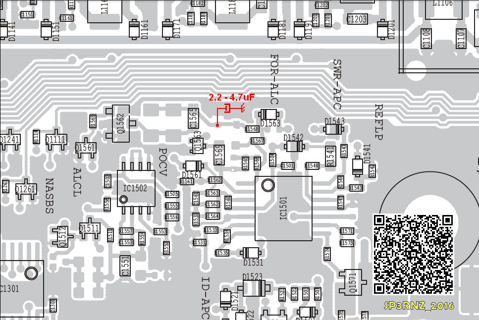
The first order of business after removing the case is to identify and prepare the location on the board where the tantalum capacitor will be installed. This is illustrated below–the first image (from Gregorz) clearly showing the board traces that are used; and the second showing them prepped for solder by careful removal of the green varnish to install the cap:
 |
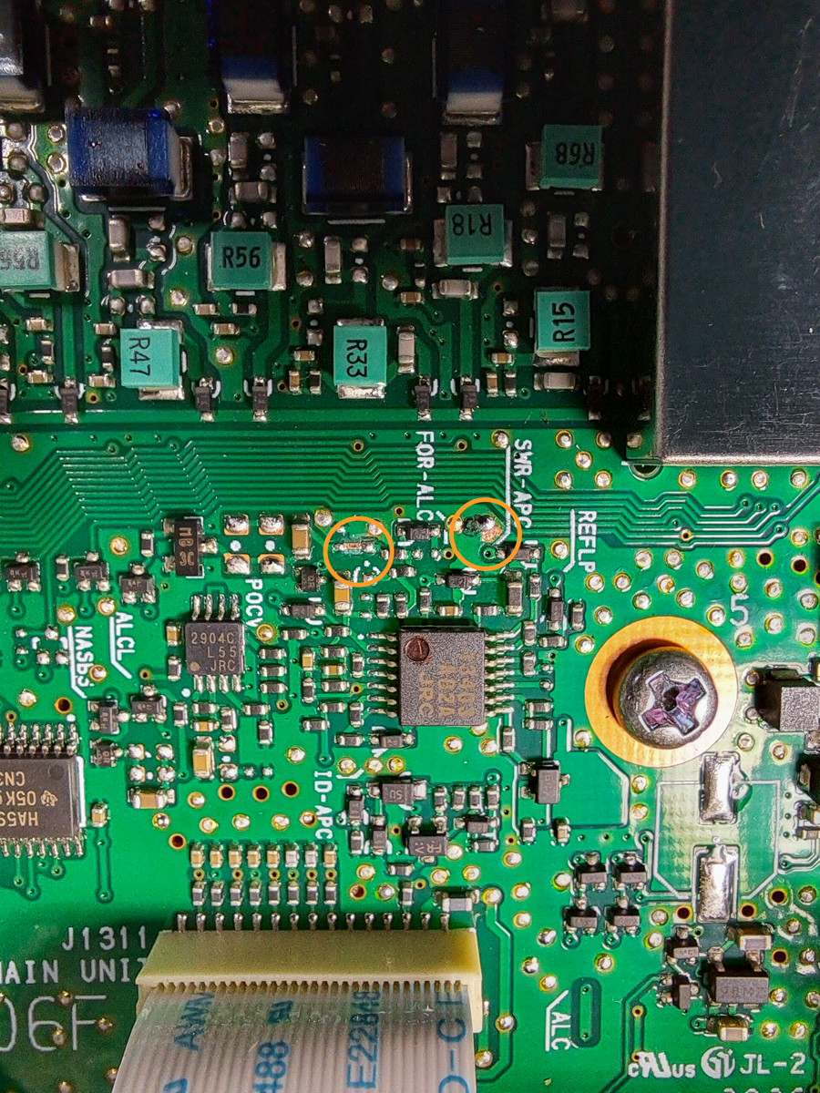 |
| Service manual image (modified by SP3RNZ) of pad placement. | Varnish is removed from traces, and ready for tinning. (AE1PT) |
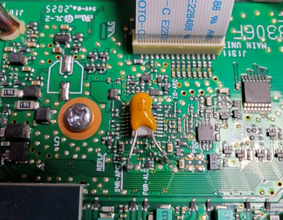
The capacitor is then soldered to to the tinned pads on the board traces. It’s always best to check for excess or tiny solder trails, beads, or flux left on the surface. Clean as necessary, and prior to reattaching the covers–test the rig out. Once there, affix the cap to the nearby 16 pin DIP with double stick tape, or a silicone based adhesive. Here is an image of the mod at the completion of the project:
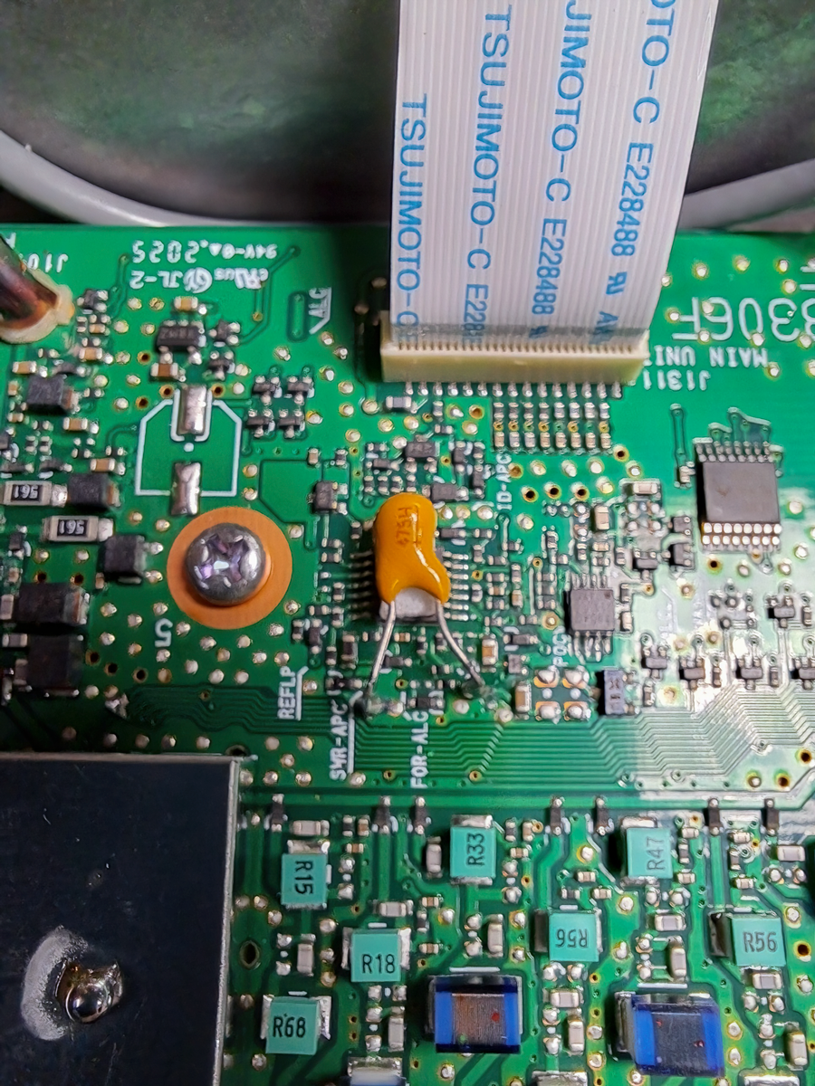
That’s pretty much it. With power output and mic gain set at 100/40% and a compression value of 1, this mod safely delivers to me a full native 100 watts with an averaged PEP output on SSB of 140-145 watts. I am considering shifting to a smaller 3.3uf capacitor, which will allow me have a broader range of mic gain, EQ and compression values, while still providing a PEP in the ~140 watt range. It’s all about experimentation, right?