

As I began planning my most recent ‘antenna farm’ adventure, the first criteria was set in that any horizontal wire design must cover at least 5 bands, with a native VSWR of no more than 2:1 at either end of any band. This can be problematic for end-to-end coverage of the 80/70M band. The second concerned impedance matching (commonly mischaracterized as ‘tuning’)–and that this transmatch be delivered solely through an Icom IC-7300 internal tuner. Topography of my property set the final factor–the longest straight wire of any nature could not exceed 134′. Overall design specifications should limit common mode issues, and construction sized for at least 250 watts PEP continuous duty.
This should not be an issue, right? After all, I had achieved this in the past with a G5RV, and another 80M doublet. Or so I believed for many years. The truth of the matter comes back to the idea of impedance matching, and the resolvable range of the L/C network.
The IC-7300 has a nominal range of 3:1 or less (~18-–150Ω) as stock. I have made the recommended modification of a 100KΩ resistor in the matching circuit, which delivers an nominal range of 6.1 or less (~8-300Ω) –without stressing the component ratings of the auto-match circuit. This radio supports an “Emergency” mode, which under a 50% power level can manage a 10:1 range (10-500Ω). In my previous shack realities, I was matching the aforementioned antennas with a Dentron MT-3000A tuner. There was absolutely nothing this beast could not match–a memorable experience loading a gutter as a “just because I can” exercise comes to mind…
My brainstorm and subsequent was an 80/20 OCF dipole. The design focus came from an article by Claude Jollet VE2DPE, discussing and charting a variety of OCF ratios. The overall performance of the 80/20% variation led me to choose it over the more common 1/3 (33/67%) or 1/4 (25/75%) varieties. This cut/tune was chosen with the modified 6:1 range of the internal IC-7300 autotuner considered. Follow the link below for more information on how OCF cuts differ–and to choose your own design:
Understanding the Design of the OCFD Antenna
After an initial bit of trimming and matching with the LDG AT-100Pro autotuner, it has eight usable bands ( 80/40/30/20/15/12/10/6 ) all with a VSWR of ≤1.8:1. Additional adjustments will be made as the wire stretches out across time.
This OCF was forged in the rain and cold with the required amount of blood slathered on it; partially hung another day until it got too dark to see, then finished next morning with below freezing temps and snow flurries. These conditions certainly contribute to why it works so well—generations of hams have always cited such things as necessary to make a top-performing antenna…
 |
 |
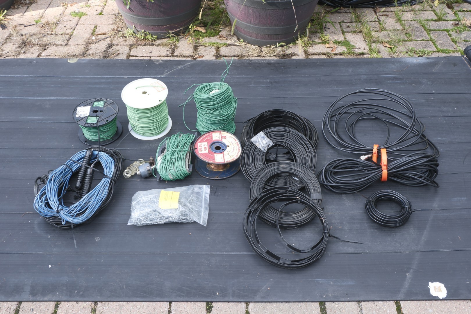
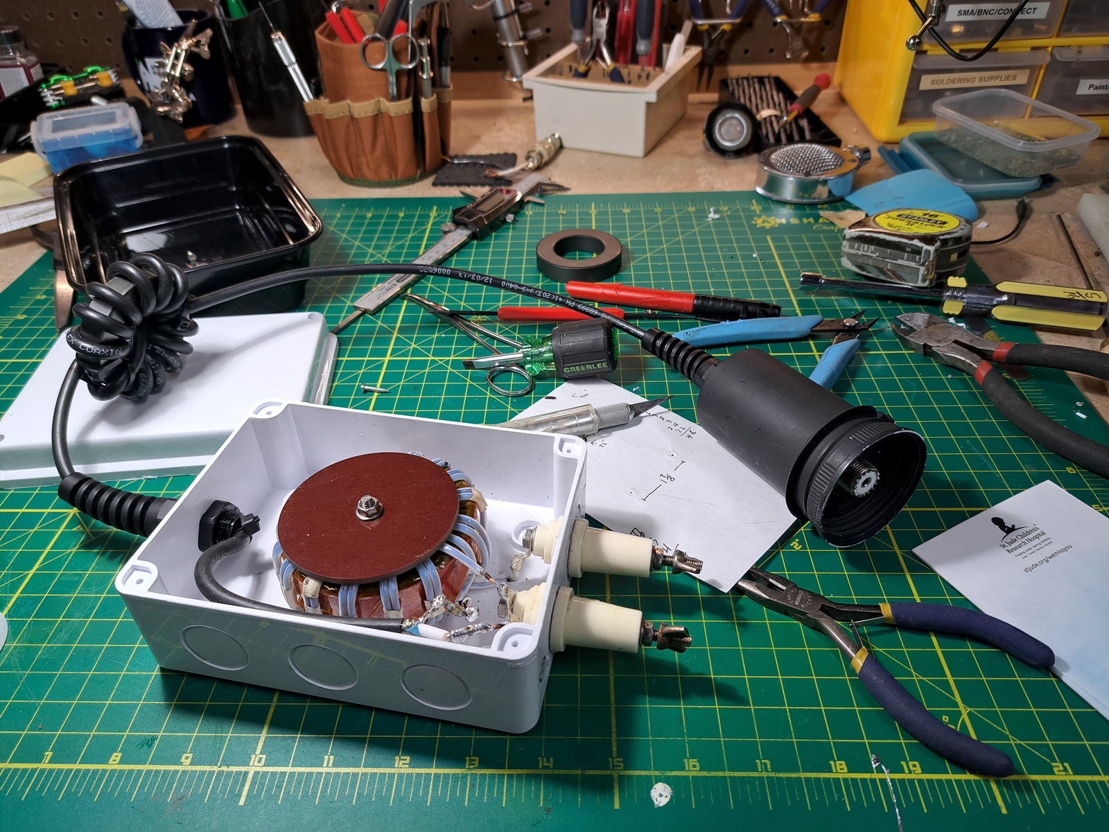
Construction as follows:
|
TA DA!
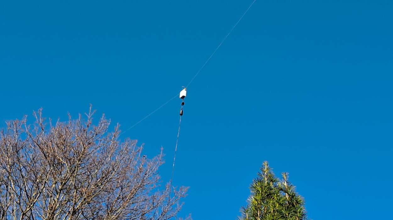
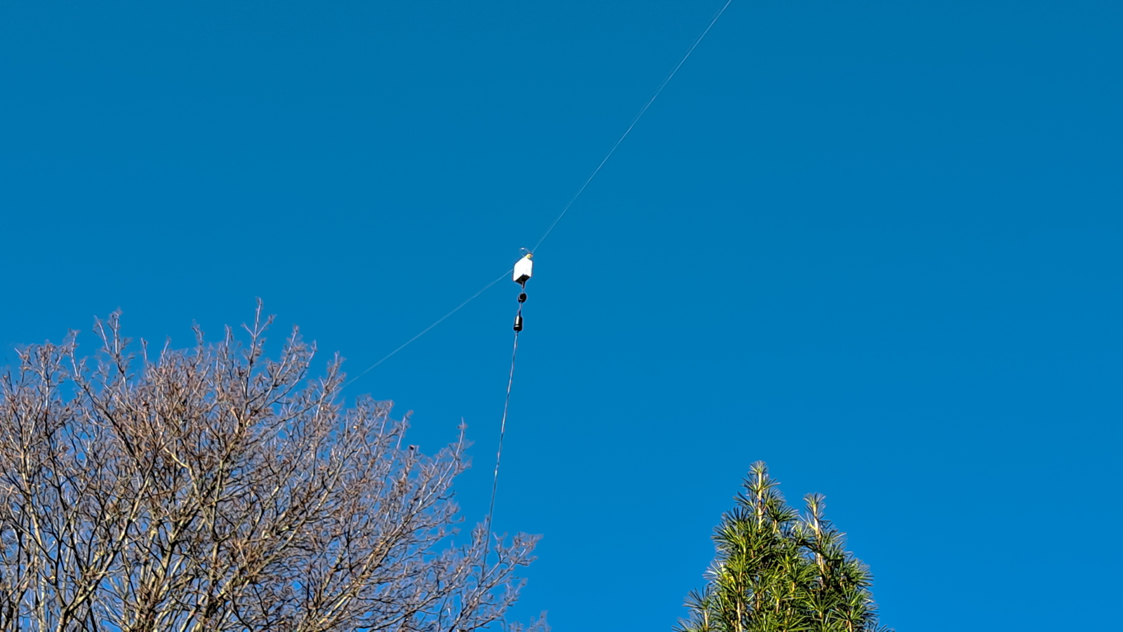
And here I have arrived an above ground level [AGL] of ~45’ on either end, with a central dip down to ~40’, depending upon how the wind is trending. My QTH is 1,102 feet (336 meters) above sea level. This image depicts the southern (common) short leg of the OCF, with the current balun and a common mode choke at the feedpoint. A similar Fair-Rite FT240-31 choke is placed near where the terminal end of the Times LM-240 ultraflex connects to the homebrew window bulkhead passthrough plate. |
Since I installed this antenna, it has since raised to 50′ AGL, and I am using an LDG AT-100Pro as an outboard transmatch. This antenna delivers consistently good signal reports–local, regional, and DX–and is significantly quieter than my 134′ doublet. I believe this one is a keeper!