
![]()
 Alright Sherman, it’s time to join Mr. Peabody and “Set the Wayback Machine” for 1970. We have arrived in an average-sized Midwestern town where we will visit two electronics operations—one a television repair shop and the other a ham radio shack. Observe closely, for we are looking for something very useful that can be brought forward to today’s electronics workbench.
Remember that these are still the waning days of the vacuum tube Solid-state is becoming more common in home entertainment applications–but for the ham, repair technician, and experimenter, much of the equipment is still firmly based on “hollow state” devices. In both the TV shop and the shack, there is one piece of equipment that holds a position of prominence at the front of the bench—the vacuum tube volt meter, or VTVM.
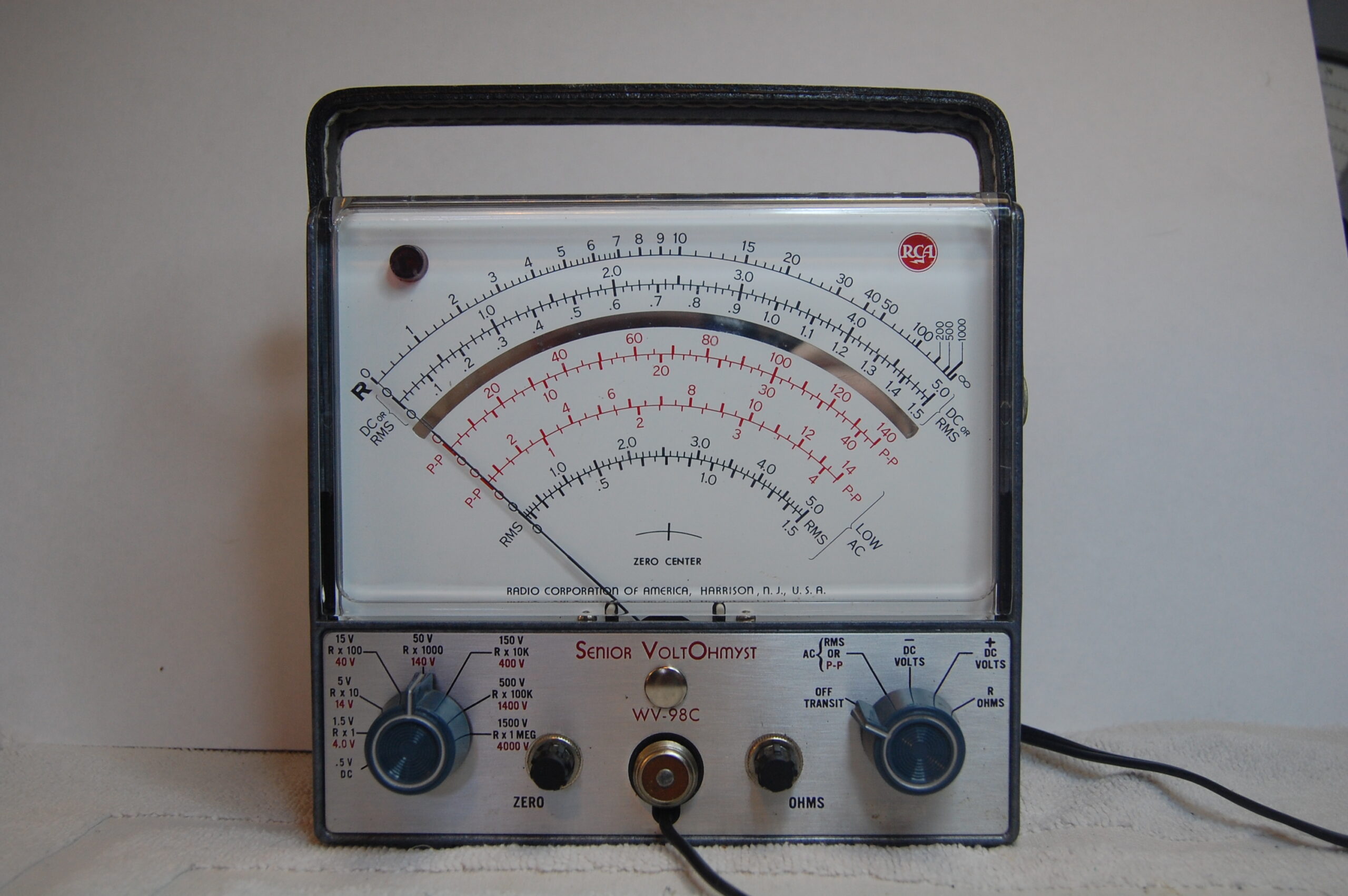
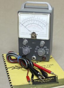
An RCA Senior VoltOhmyst holds court at the TV shop, while a Heathkit IM18 built by the amateur presides in the shack. While these two meters look quite different in shape, the surprise is that they have essentially the same circuit inside. In fact, the VTVM has changed little in its design since it was first introduced in 1916. Below, see a schematic for a typical simple VTVM:
Having identified our historic prize, we move forward to the present time and examine what a VTVM can do for us today. After all, are not our modern digital (DMM) and analog (VOM) multimeters much more accurate and versatile? As we will discover there are many things that one can accomplish with a VTVM that simply cannot be done reliably or with the same degree or responsiveness as with more modern equipment.
The first task of course is to get one of these handy instruments into our possession. A quick way to find anything is to check eBay. A search of completed auctions reveals that several different brands and models can be had ranging from $10-50 in price, with $25 the average cost. Other sources can be hams that are not using these anymore, estate sales, and hamfests.
Make sure that the meter you are considering has its probes, powers on, and preferably has a manual. Quite a few brands are available. A short list of the most common include RCA/VIZ, B&K, Knight, Heathkit, Eico, HP, Simpson, Triplett, and others. Test equipment manufacturers frequently offered several kinds of accessory probes to round out the capabilities of the VTVM—very similar to those found for oscilloscopes.
These included high voltage, RF voltage, demodulator, and even specialty probes for temperature and the pH of solutions. Due to the universal design of many VTVM’s, these probes will often work across brands and models. Note that older VTVM’s produced prior to the 1960s lack two important features. First, they do not measure resistance—scales only reflect voltages and decibels.
Second, in the early 1960s a 1.5 volt scale was added to improve accuracy when measuring smaller voltages (even a .5 volt scale in some cases). A few models of older VTVM such as the Hewlett Packard 400 series actually had a vacuum tube in the probe itself. Another limitation is that the test leads were usually an integral part of the unit—hardwired to the circuitry through the front panel and not interchangeable. While these meters can be made fully functional for today’s bench, it is recommended that a more recent and versatile vintage such as the RCA/VIZ WV-98 series be selected.
 Now that we have a VTVM on the bench, the real question becomes what can we do with it that our DMM or analog VOM is not capable of? To answer this question let’s first look at how the VTVM works. Essentially, the VTVM uses a dual triode vacuum tube (usually a 12AU7) in a balanced bridge circuit to amplify incoming voltages. This sort of design provides several useful functions. A diagram detailing the most common VTVM circuitry is shown at the end of this article (RCAWV98C).
The first is that a very high impedance (approximately 10 MΩ) is shown to the circuit under test. This provides a high degree of isolation between the metering circuit and the test circuit—resulting in a very low “load” placed into the tested circuit. Such a configuration is very convenient in low power, coupling, amplifier, and resonant circuits as it does not change the operational characteristics of the circuit. This characteristic is shared by many quality digital meters.
A high degree of amplification in the metering circuit also means that very high resistances up to 1000 MΩ can be measured. This is useful in determining dielectric resistance, leakage of capacitors, transmission line characteristics, and isolation leakage. The amplification factor is also beneficial when measuring small audio or IF voltages, giving one a true indication of the performance of the circuit under test.
A unique ability that a VTVM has that a DMM or VOM does not is to read AC voltages in both RMS (root-mean-square) and PP (peak-to-peak) values. The common DMM/VOM averages the AC sine wave and delivers an RMS approximation of the voltage. By using PP voltage measurement, more complex sine waves and other waveforms can be accurately measured—the added benefit being that the PP measurement coincides with how an oscilloscope measures voltage. Combining the VTVM with a scope delivers waveform observation that shares the same measurement standard.
The voltage measurement of complex sine patterns or other forms such as square or sawtooth is best accomplished with the VTVM. In situations where there are likely to be rapid variances and transient spikes present in the signal, the VTVM shines with its rapid response and ability to correctly decipher the correct voltages at hand. This instrument is also relatively immune to false indications due to interference and strong electromagnetic fields.
It is also much easier to determine the minimum and maximum changes in a circuit by following the meter needle than trying to make sense of a wandering digital display. This alone eases any receiver alignment process.
Here are a few of the better uses of your VTVM:
- Measuring coupling and other capacitor leakages
- Troubleshooting audio circuits
- Measuring voltages in tuned and resonant circuits
- Determining reactance and inductance of components
- Alignment of tuned circuits
- Measurement of potential 1500 V and above (with proper probe)
- Direct measurement of high-frequency voltages
- Ability to measure DC in the presence of AC voltages
As mig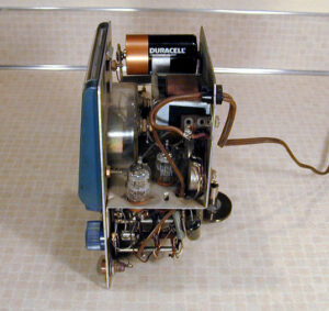 ht be expected with any older test equipment, your “new” VTVM will likely need a little servicing before it can serve reliably on your bench. All paper-based capacitors over time will become leaky—and require replacement. Depending upon the age of your unit is may be wise to simply replace the coupling and any electrolytic capacitors that may be present in the circuit.
Rotary control switches and adjustable potentiometers become dirty through oxidation and atmospheric contamination. These should be cleaned with a quality spray on cleaner/lubricant or an application of a solution such as DeoxIT. This applies to calibration trimmers as well—a thorough cleaning and recalibration as given in the instruction manual is recommended. This should be done every several years—and is solid practice for all your older test equipment.
Interestingly, quite a few VTVMs used a battery to supply the resistance measurement voltage. A first check of the interior of the meter will look at replacing this battery and repairing any damage done by leakage of an old cell. Some enterprising technicians have tapped into the tube filament voltage to feed a circuit that provides a stable 1.5-volt DC supply—thus eliminating the need for a battery. This will be covered in a later project and article! Once the dominant instrument in any electronics shop, the venerable VTVM still has a valuable place on the radio amateur’s bench.
Although it has been many years since the majority of VTVMs were made, a wealth of resource materials are still available to the bench technician and hobbyist. A quick search of Amazon.com turned up nearly 20 unique used books detailing meter operation and a variety of troubleshooting techniques.
The most complete reference for these meters is “The VTVM” by Rhys Samuel. Originally published in the mid1950s, copies in hard and soft cover are still available at a reasonable price. As noted, it is important to have a manual for your VTVM. If one did not come with your meter, multiple online resources exist that will provide you with one—as well as servicing and operational tips. There are even several YouTube videos that detail the rehabilitation and calibration of common VTVM units.
Here is a list of resources for the new VTVM user:
Books
101 Ways To Use Your VOM and VTVM Robert G. Middleton, 1959
Troubleshooting With The VOM and VTVM Robert G. Middleton, 1962.
Know Your VOM-VTVM Joseph A. Risse, 1963.
The VOM-VTVM Handbook Joseph A. Risse, 1972.
On The Web
BAMA Manuals & Schematics
http://bama.edebris.com/manuals/
VTVM Restoration, Alignment, and why you should own one
https://www.youtube.com/watch?v=GR3rR7tc30Y
An Idiots Guide to VTVMs
![]()