

[This is a developing story that will take several weeks months. Progress will be updated regularly!]
I have four microphones. Then there are inputs for computer sound, CW keying, and other external audio. The mics are a mix of electret and dynamic types–meaning that the latter must be isolated from the 8VDC electret supply–and run through a preamp as well. All of this has resulted in a nest of tangled wires that sometimes seemingly defy being sorted and selected. Forget about changing something mid-net even with color coding connectors…
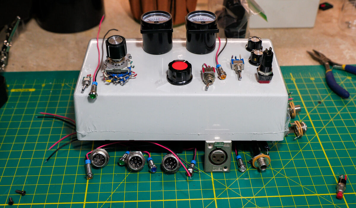
It occurred to me some months back that I needed a breakout box, one that would handle multiple 8 pin aviation connectors, classic 4 pin configurations, 1/4″ & 3.5mm phone plugs, and 3 pin XLR bulkhead connection–with and without 48VDC phantom power. It would be really nice for it to also handle internally all preamp & mic power functions–as well as incorporate central PTT control and CW functions. Yeah, a code practice oscillator and a 1-2 tone test signal. Perhaps some cool VU meters to display the levels. And probably something else I can squeeze in there–that is yet to occur to me. A tall order, am I right?
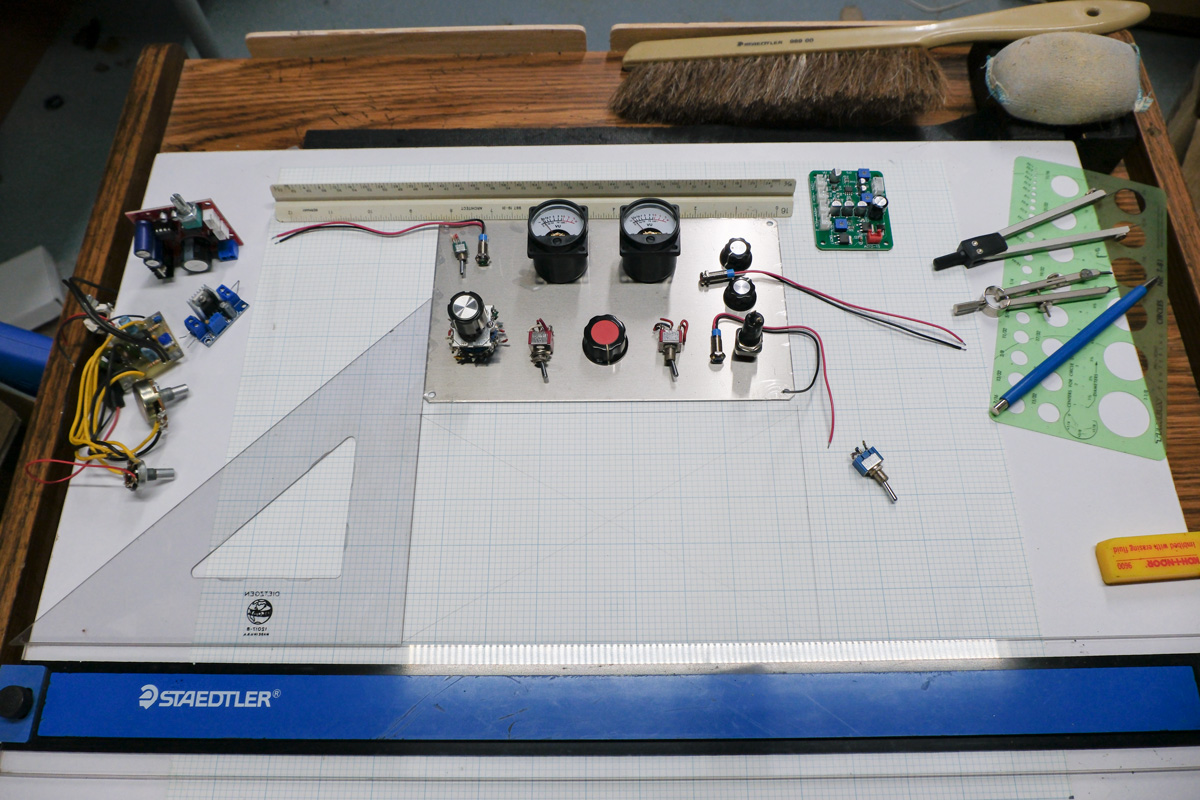
So in April of 2026, I began scrounging parts from various basement shop parts inventory, derelict old electronic gear and junk boxes. Then assessing and ordering wonderfully cheap Chinesium circuitry and acquiring missing components. Amazon and Digi-Key were my usual friends–they surely like my money. Now comes the challenge of putting it all together into a gestalt final form. The header image sets forth the overall 3D layout process for the sloped Hammond box everything will go into. The second image details the actual panel layout process–whereby physical placement is translated into an overlay template for package cutout.
The recycled double stack 5 position rotary switch will provide the input selection. The second switch deck (or wafer if you prefer) sends power to an LED that is to be mounted next to each input. There will never be any doubt as to what mic or input is live. Combined with several DPST switches (added and swapped in since the photo was taken), similar LED switching occurs indicating what other processes or power deliveries are active.
Pictured below is the projected panel layout, ready to be translated to the template drawing below. Circuit boards shown running clockwise from the left; code oscillator and tone generator; DC-DC buck converter; two channel preamp board; VU meter driver board.
Watch for updates, as this true ham homebrew adventure moves along!